Sireum Awas Documentation
2. Sireum Awas Visualizer
2. Sireum Awas User Stories
Sireum Awas visualizer is an HTML5 based web application providing dependency graphs for AADL systems. Combined with a simple abstract interpretation engine enables a user to explore and understand an AADL Model, follow component connectivity, perform risk analysis and secure information flow analysis.
Demo Awas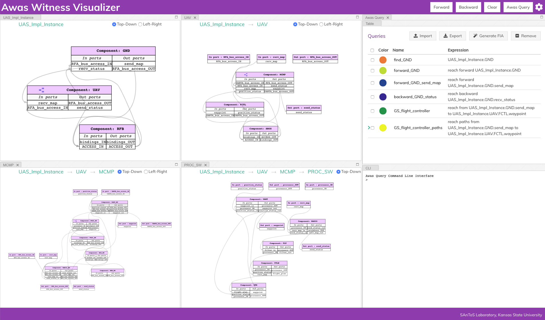
2.1. Sireum Awas Capabilities
Model Navigation: Enables a user to explore a system’s model without installing modeling tools. Provides the freedom of referring the model from both handheld devices and desktops. The user can hide irrelevant part of the model and focus on a specific level of modeling detail
Dependency Analysis: A system is a composition of components and Awas provides insight into the interaction of components through component connectivity(inter-component dependency). Along with the interaction of ports within a component(intra-component dependency)
Risk Analysis: AADL Annex Error Modeling Version 2(EMV2) provides a mechanism to specify the error behavior of a component using abstract error tokens. Awas visualizes the propagation of errors in a system. Furthermore, Awas helps in finding the root cause of a hazardous system state which may lead to an accident
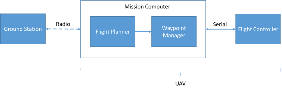
2.2. Simple UAV System
In this section, we illustrate a simple UAV surveillance system that is used as a running example to demonstrate the capabilities of Awas.
This system consists of a ground station and an Unmanned Aerial Vehicle(UAV). The primary function of this UAV is to conduct surveillance over a specified region. This UAV receives the region information, for instance, a map with the target location and obstacles, from a ground station. In turn, the UAV sends back status information.
This UAV consists of a mission computer and a flight controller. The purpose of the computer is to compute a set of waypoints(GPS coordinates) from a map and a flight pattern provided by the ground station. The flight controller acts upon these waypoints to progress on the surveillance task. The UAV sends a corresponding status code to the ground station whenever it reaches a waypoint.
2.3. Model Navigation
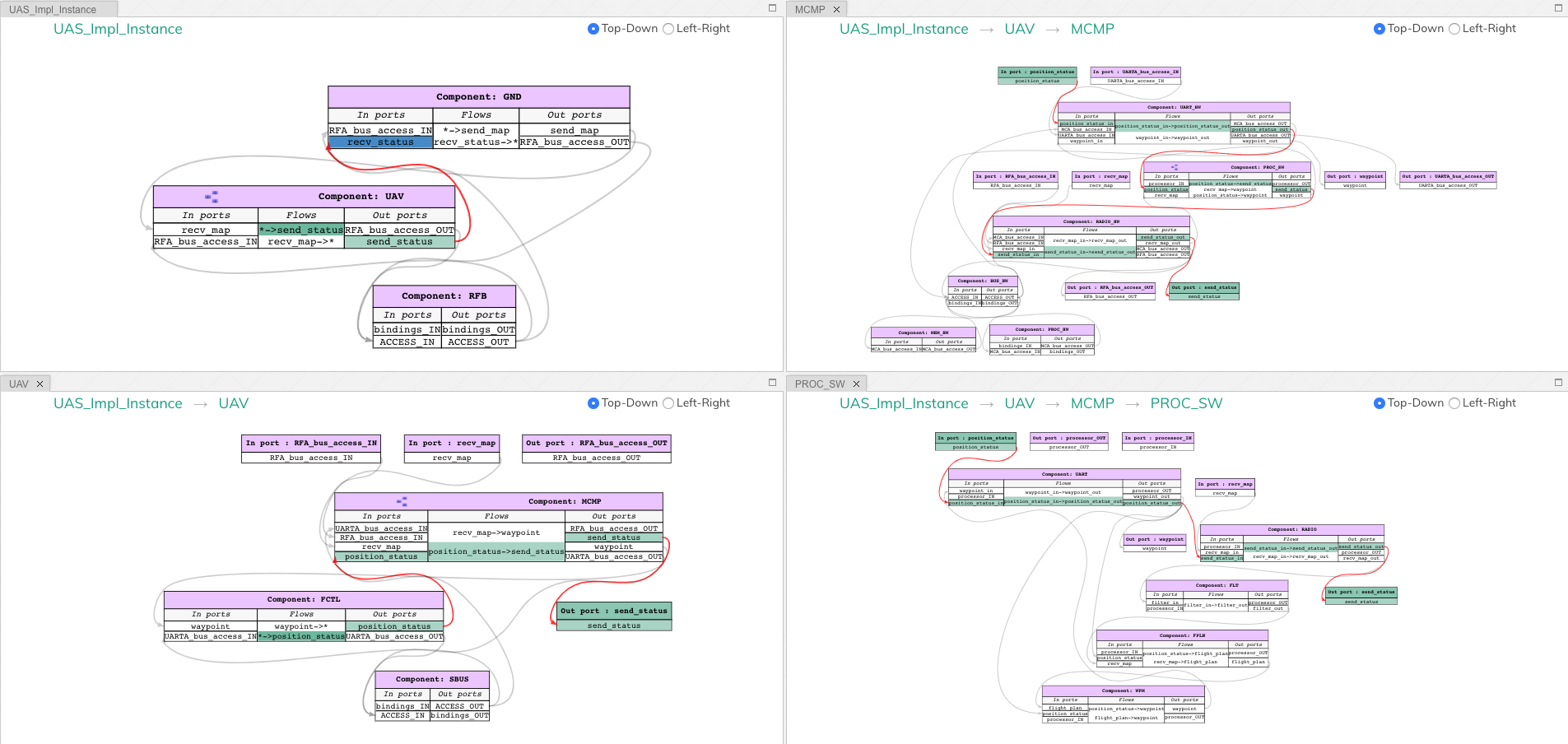
OSATE can produce a system implementation diagram from an AADL system. The following section provides a side by side comparison between AADL instance diagram and Awas graph for the four systems of the UAV surveillance model.
2.3.1. UAS: The top level system with ground station and UAV
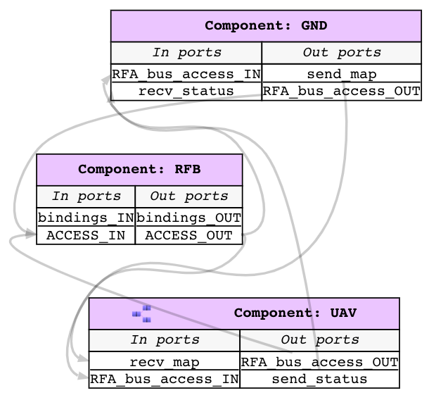
Both the AADL diagram and the Awas graph consists of three components namely GND, UAV, and RFB. However, in the AADL diagram the different types of components are differentiated by different component shape. Awas does not distinguish between the types of components. However, Awas explicitly segregates input and output ports. For in-out ports, Awas creates two ports one for input and the other for output. Thus you can see there are two RFA ports in GND component in the Awas side and only one in the AADL side. Awas also separates the bidirectional connections into two separate connections.
Awas provides the following model navigation capabilities over OSATE:
In Awas, the diagrams are interactive. On clicking a node(component and connection), port, or an edge the section of the graph is highlighted
By default an edge represents an AADL Connection. However, this can be modified by the view settings.
Awas will highlight an edge along with the ports involved in the connection when clicked. Although AADL diagrams can have cleaner layouts, the edges involved in complex systems tend to overlap in AADL diagrams which can make it tedious to trace an individual edge.
- This icon
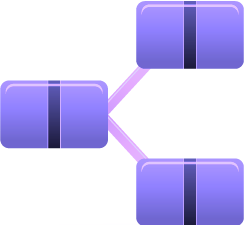 in front of a component name
indicates that this node contains a sub-system. By double-clicking on this node, you can open the sub-system's graph
in front of a component name
indicates that this node contains a sub-system. By double-clicking on this node, you can open the sub-system's graph
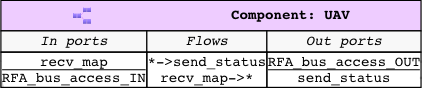
2.3.2. UAV - Composed of Mission computer and Flight Controller
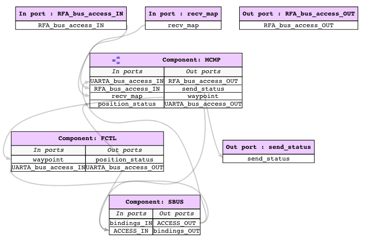
In a sub-system graph, Awas creates the parent component’s ports as
nodes. The node recv_map is same as the port in the UAV component
from the UAS system. Therefore, when clicked on either one of the
port, highlights the port in both the graphs.
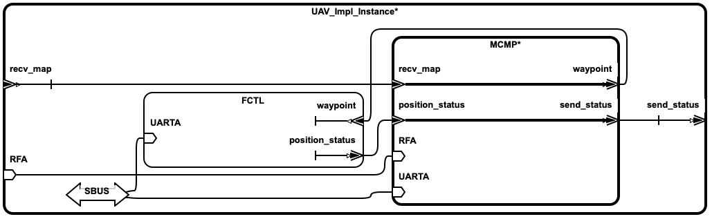
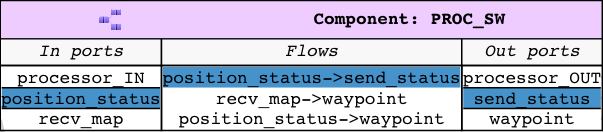
2.3.3. Mission computer - Composed of Radio, UART and Software Components
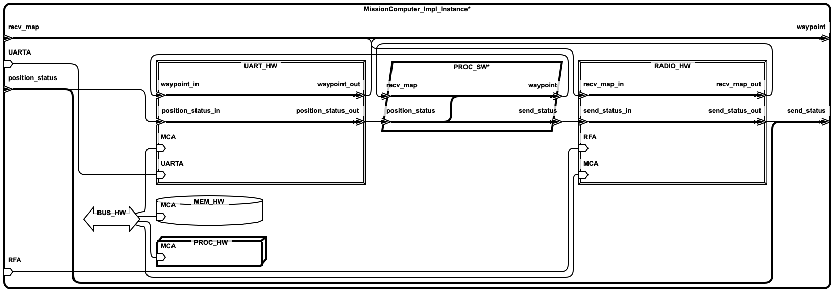
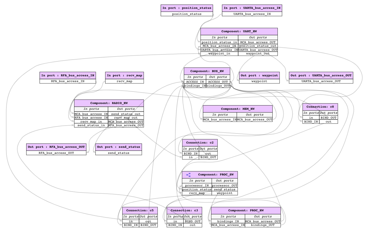
Awas graphs typically contain more edges compared to AADL
diagrams. The additional edges capture the binding relationships
between components. For example, the component PROC_SW has two
ports processor_IN and processor_OUT connecting the component
PROC_HW. These edges capture the relation that the PROC_SW
representing the software of the system executes on the hardware
PROC_HW. However, AADL diagrams fail to capture these binding
relations and the non-trivial information flow through them.
2.3.4. Software - Composed of drivers and logic for computing the waypoints
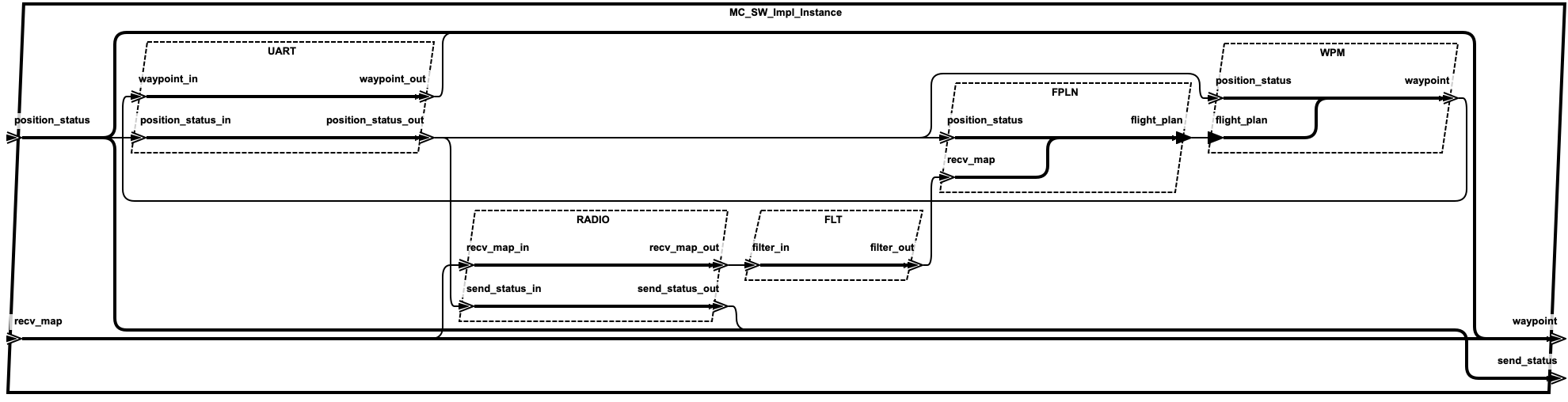
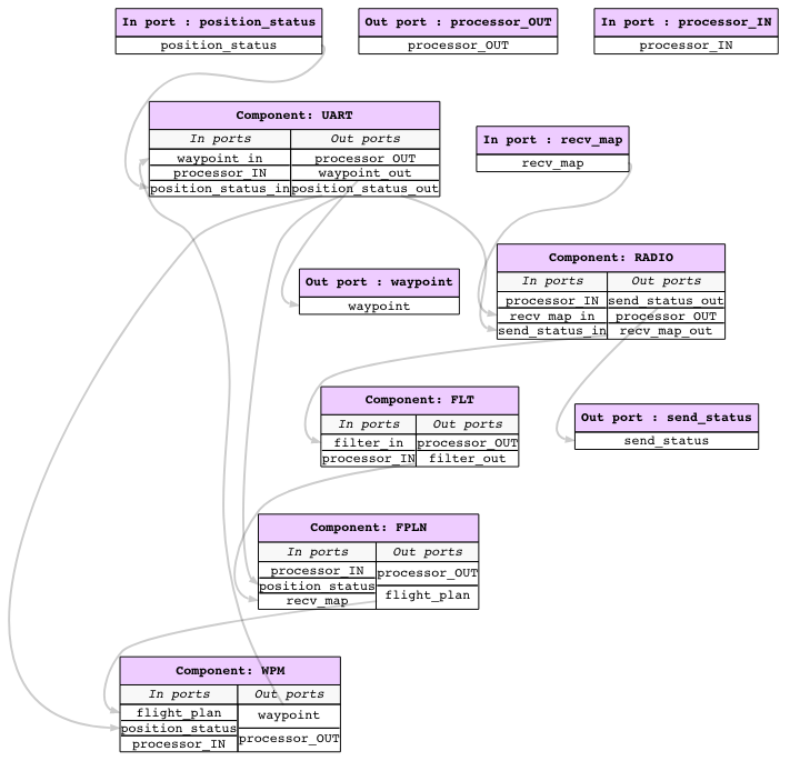
The Software system consists of drivers RADIO and UART that
communicate with the ground station and the flight controller
respectively. Apart from the drivers, the software system consists
of a filter FLT that checks the wellformedness of a map, and the
components to convert the map into waypoints.
2.3.5. Awas Visualizer Interface
At the top of the Awas visualizer page, there are five buttons. The
first one from the right is the Settings button to control the
amount of information displayed in the Awas graph. The next button is
the Awas Query button used to open the query interpreter and the
results table view. The next three buttons are dependency analysis
buttons discussed in subsequent sections.
Below the top bar is the Awas graph viewer. Each system in the AADL becomes an Awas Graph, and Awas allows the user to view multiple systems at the same time by reorganizing the graph viewer window. The top left of the graph viewer contains a breadcrumb trail that displays the hierarchy of the current component in relation to the system’s structure.
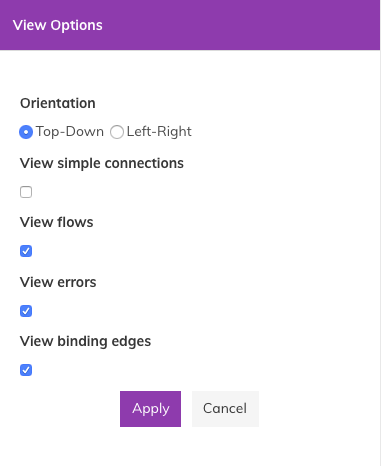
2.3.6. View Options
The View Option panel provides the ability to choose what information will be present in the Awas graph.
Warning
The view binding edges option in the view options panel modifies the underlying graph data structure. On large graphs, this toggle may take a few seconds to complete. Also, do not perform path queries in the presence of a large number of binding edges. Doing so may take a long time to evaluate a path query.
2.3.6.1. Flows
Flows are the AADL construct proving the intra-component dependencies by relating a component’s input and output ports.
By selecting the checkbox in the settings view, one can view the flow information in components.
In AADL there are three kinds of flows.
Flow source - Information originates within a component and flows out through its output port. For example, in the flow
* -> send_statusthe* ->indicates that the information flowing out of the portsend_statusoriginates within the componentUAVFlow sink - Information flows into a component but does not flows out instead the component consumes the information. Similarly, in the flow
recv_map -> *, the-> *indicates that the information received on portrecv_mapis consumed within this component or the subsystemFlow path - Information flows into the component may be just propagated out or transformed and propagated through the component. The symbol
->indicates the relation between the input and output ports of the component
By clicking on a flow, Awas can reveal the relationships between flow and the ports of a component.
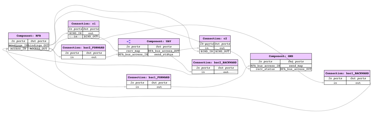
2.3.6.2. Connections
In AADL, a user can add flow relations to a connection indicating the information that influences the communication substrate. The AADL instance diagram fails to capture these flows. In Awas, users have an option to view or hide this information. Similarly, connections and the underlying communication substrate exchange information through the bindings relations that is missing in AADL instance diagram. Again, Awas provides an option to view or hide these bindings relation.
2.4. Dependency Analysis
In model-based design, the primary functionality of a designer is to translate the system requirements into models. High level requirements are the connectivity among components. Awas can help in checking if the connectivity requirements are translated to the design.
2.4.1. Forward and Backward Analysis
Awas can do two kinds of fundamental dependency analysis based on the direction of traversal. The user can use them to answer specific questions such as the following:
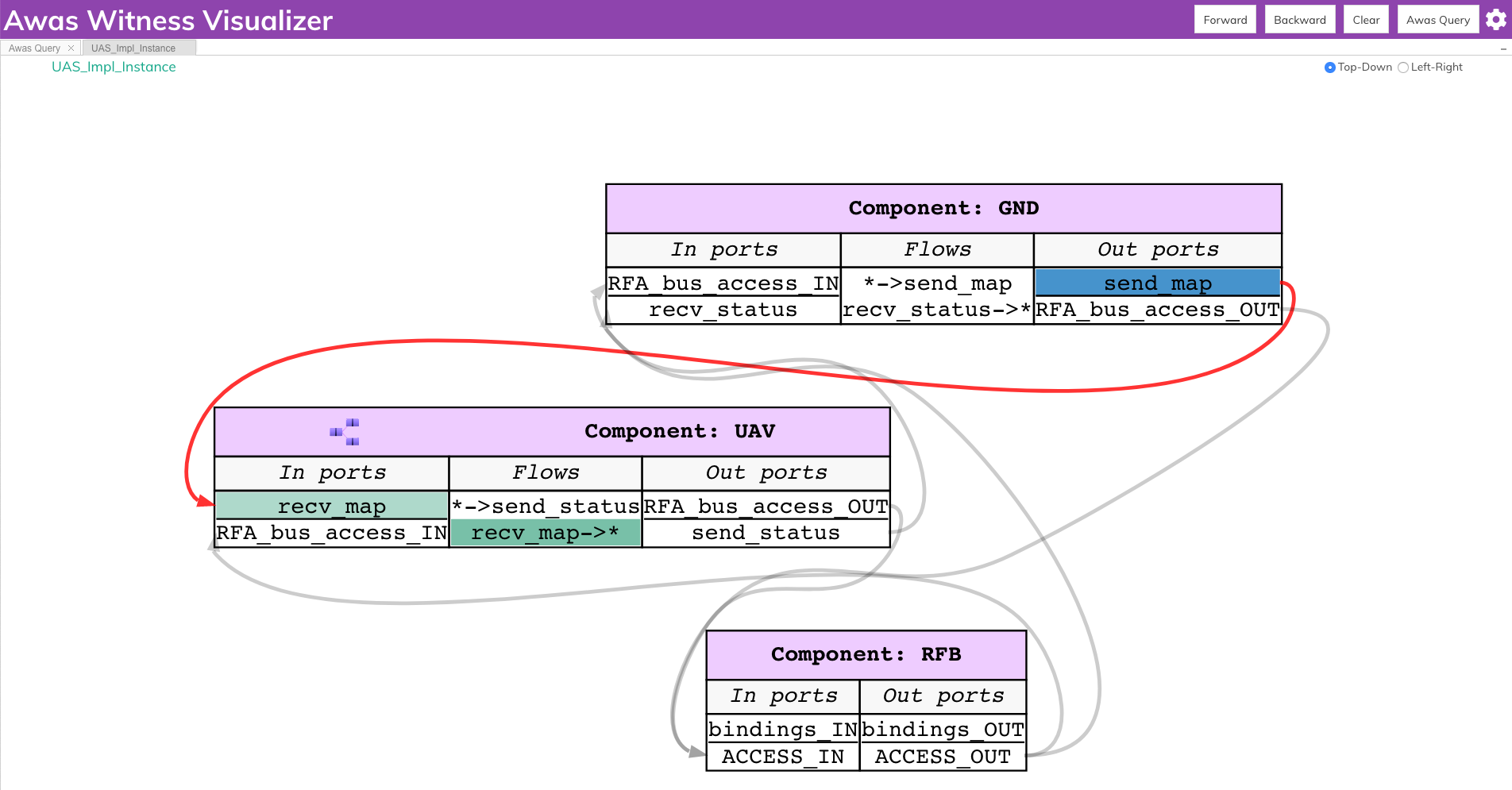
- Query 1
If the ground station sends the map, Where does information regarding the map flow? Also, where is it getting consumed?
The answer can be obtained by selecting the port
send_mapin the component ground station and clicking theForwardbutton on the top of the screen. This action highlights all the ports that receive the information fromsend_map. The flow highlighted with a darker shade indicates the consumption of this information. If the user wants to go down the hierarchy, they can double click on theUAVcomponent to see the influence ofsend_mapin the subsystems.
- Query 2
From where does information needed to compute the
recv_statusflow from?The user can select the port
recv_statusand click on theBackwardbutton on the top right of the screen. This action highlights all the ports through which the information needed byrecv_statusflows. Also highlights the flows that source the information in a darker shade.
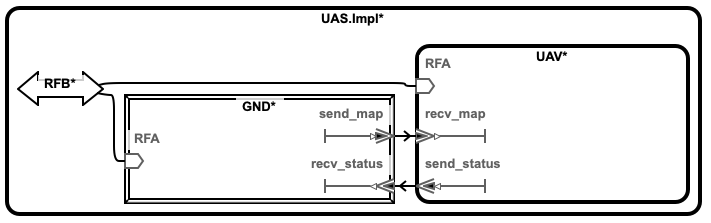
2.4.2. Forward and Backward Analysis in OSATE
Along with the visualizer, Awas is also integrated with the AADL instance diagram. OSATE can generate different kinds of AADL diagrams, among them instance diagram shows a specific composition of the components in the system.
The Awas plugin provides these icons in the AADL diagram views. They correspond to the forward reachability, backward reachability and erase results. The user can
select a component or port in the AADL instance diagram and on clicking the forward or backward reachability icon, the Awas
computes the reachability and highlights it on the instance diagram.
in the AADL diagram views. They correspond to the forward reachability, backward reachability and erase results. The user can
select a component or port in the AADL instance diagram and on clicking the forward or backward reachability icon, the Awas
computes the reachability and highlights it on the instance diagram.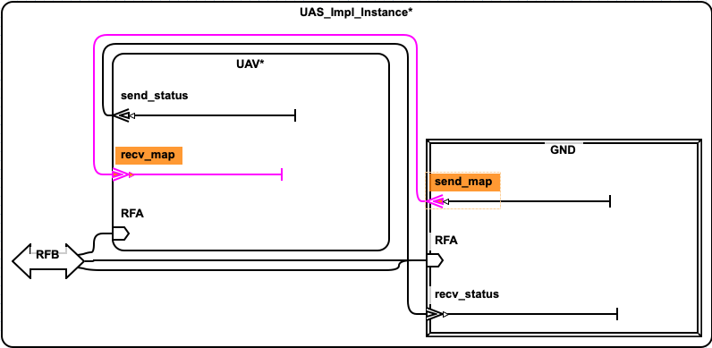
The above image show the result of performing a forward reachability
from the send_map port in the GND component. Awas computes
port level reachiability and highlights the connections and ports that
are reachabile form the send_map. AADL allows user to open the
subcomponents by right clicking on the corresponding component and
clicking show contents.
AADL diagrams allows precise customizations of the diagram by hiding or showing to get only the interested parts of the system to be displayed. Similar to the forward reachability, bacaward reachability can be performed from any port or component in the instance diagram. The user can export the diagram along with the result of the reachability in to images to include it in other reports.
2.4.3. Dependency Analysis Using Queries
While performing backward and forward analysis is quick and
straightforward using the buttons, it is not easily reproducible by an
automated regression testing suite. To remedy this, we provide a
simple query language an interpreter inside the Awas visualizer. To
open the query interpreter, click on the Awas Query button on the
top right corner.
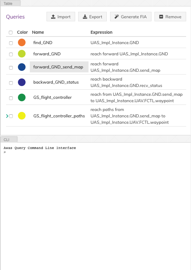
The query view tab contains two additional tabs:
Table
The
Tabletab lists the previously executed queries. The color in front of each query name indicates the result highlight color. Clicking a query name will highlight the query result in the graph.CLI
The CLI provides a terminal for entering the queries. If there exists a solution for the query, the list of graphs containing the solution is presented. Also, Awas creates a table entry in the
Tabletab and stores the result.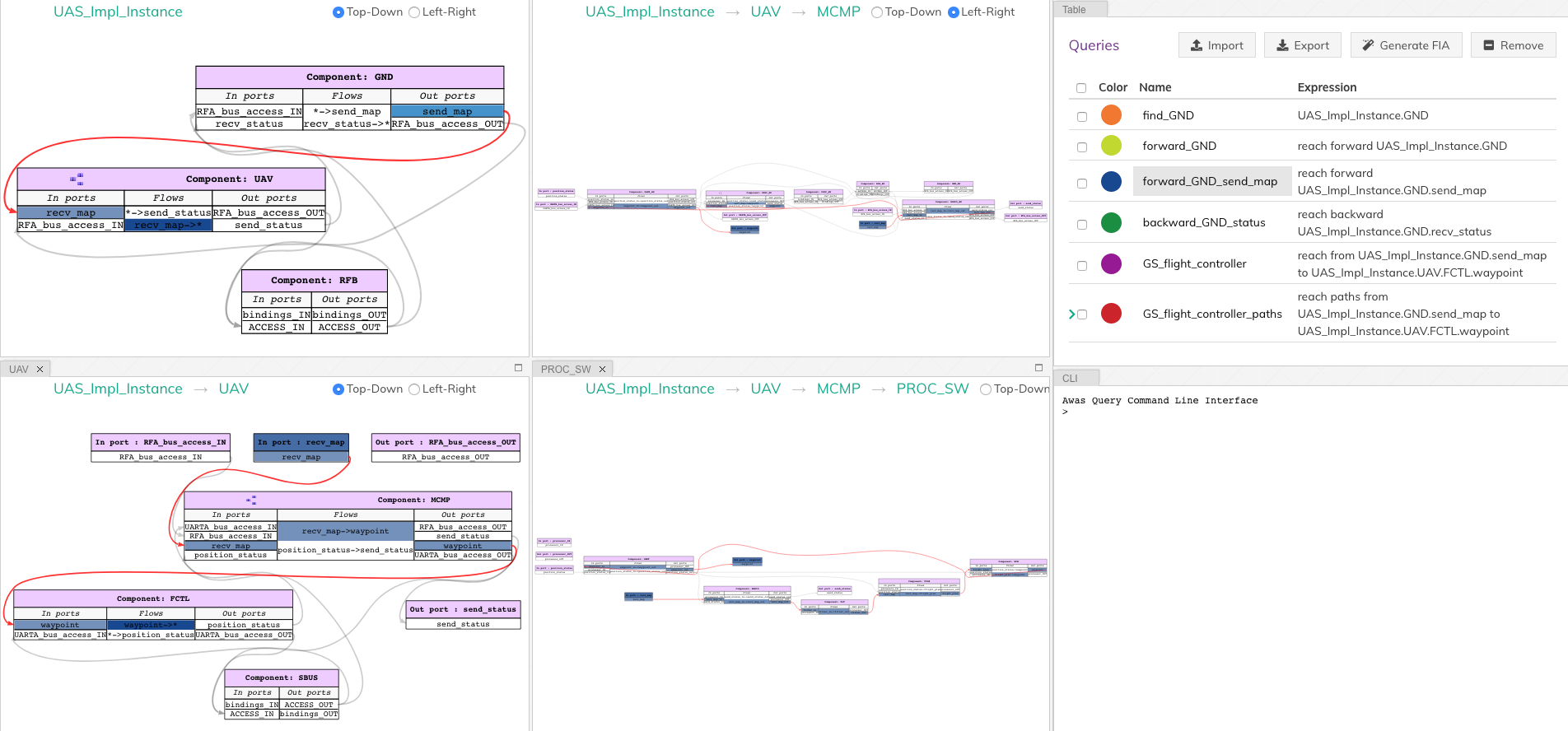
The query
forward_GND_send_mapperforms the same operation of the Query 1.forward_GND_send_map = reach forward UAS_Impl_Instance.GND.send_map
In this query statement, the term before
=is the name of the query and everything else is the query expression.After the
=, there are only two possibilitiesPrimary Query Expression:
This can be a canonical representation of a node, port, or an error token or a previously executed query name.
Reach Expression:
All reach expressions start with the term
reach,and the term after thereachindicates the direction of reachability and the rest of the expression identifies the canonical representation of the portsend_map.
Note
Awas query expressions are case sensitive.
2.4.3.1. Multiple Query Results
The last button to discuss at the top right corner is the Clear
button. This button’s purpose is to clear the highlights on the
graph. However, it can be useful to view the results of multiple
queries at the same time.
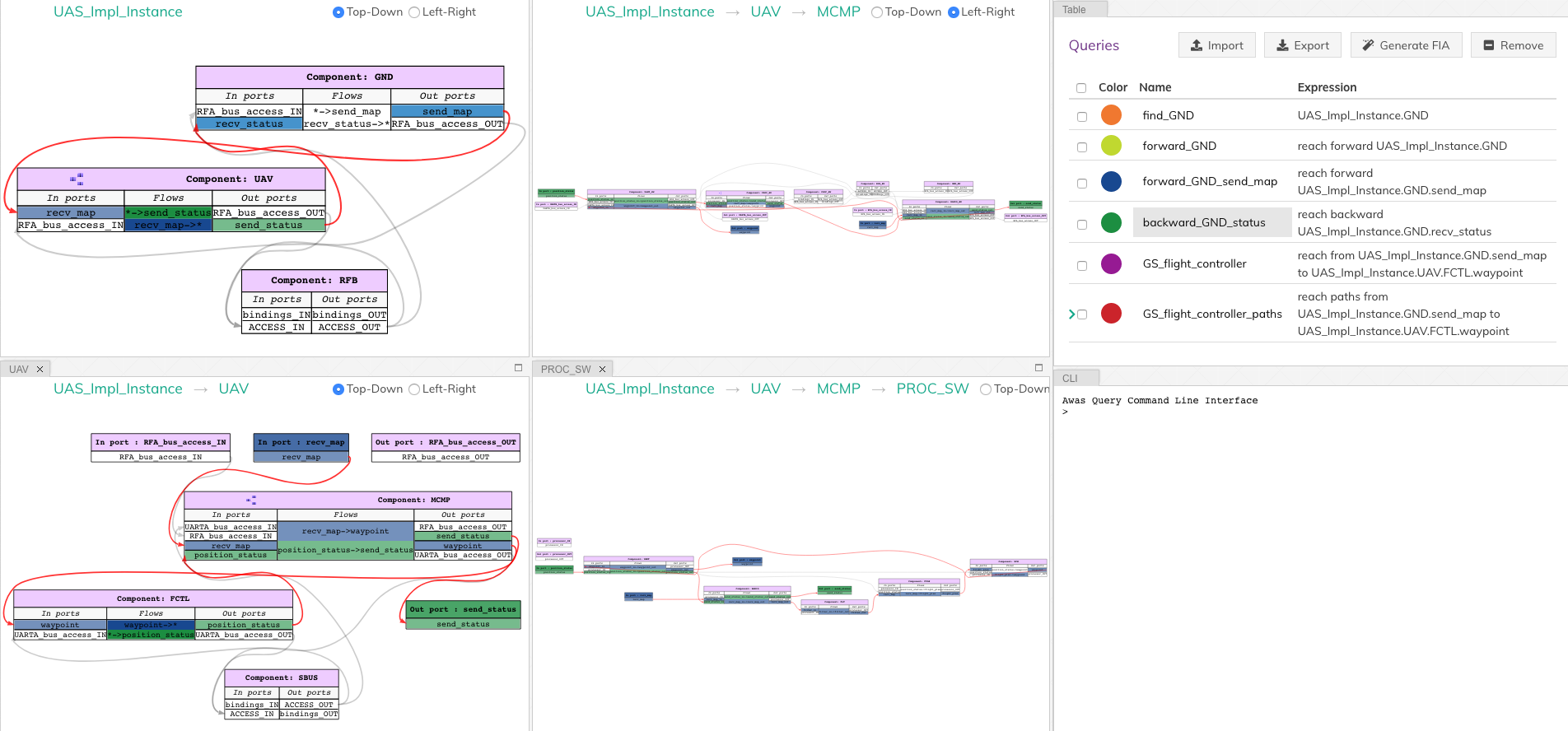
The query backward_GND_status performs the same action as the
Query 2. By clicking on the button backward_GND_status without
clearing the result of the previous query we can see the results of
both the queries.
backward_GND_status = reach backward UAS_Impl_Instance.GND.recv_status
|
2.4.4. Complex Queries
The query language’s capability goes beyond the simple queries. Using the queries, the user can compose much more interesting questions.
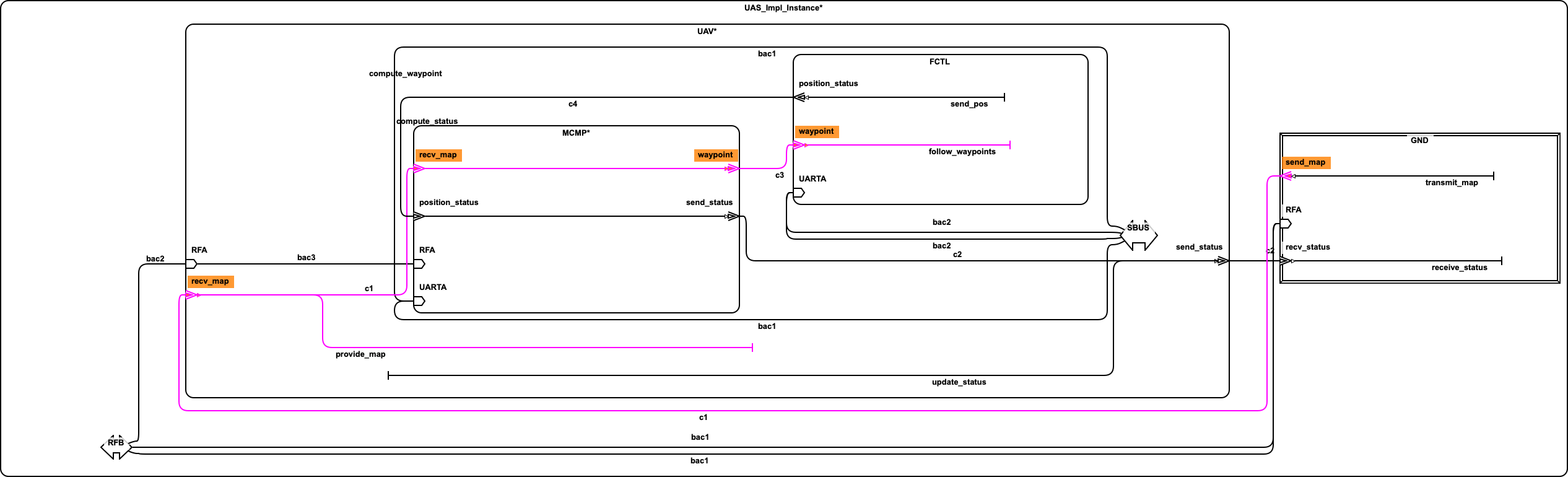
- Query 3
when the ground station is sending the map, how does it get to the flight controller?
The striking distinction between Query 3 and the previous queries is the number of arguments in the query. In this query, the user asks if it is possible to reach the flight controller from the ground station, show how it is possible? In contrast, the previous queries only showed how the information flowed into or out of a specific node, port or error token.
2.4.4.1. Source to Destination Query
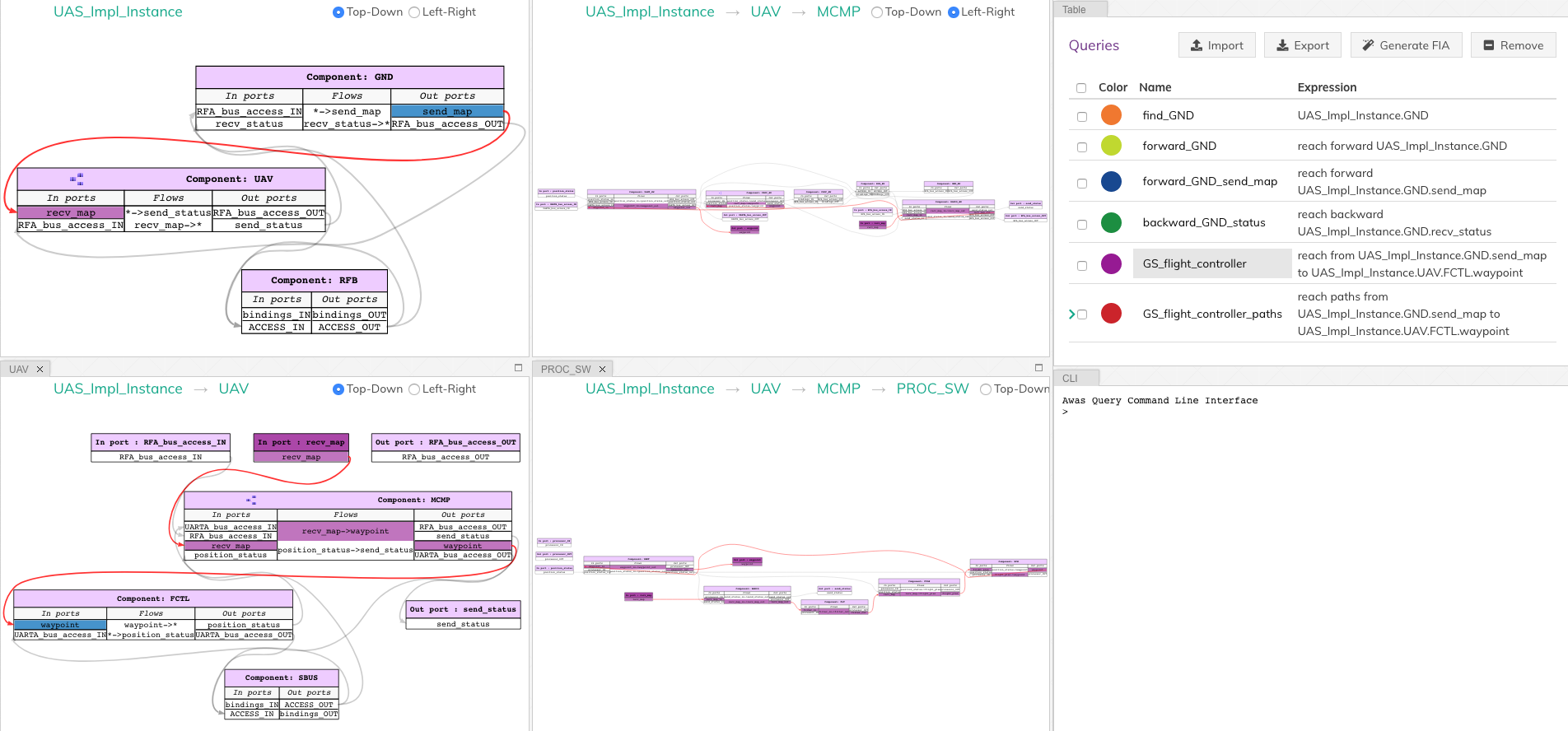
The following Awas query statement captures the user’s Query 3
GS_flight_controller = reach from UAS_Impl_Instance.GND.send_map to UAS_Impl_Instance.UAV.FCTL.waypoint
|
This is again a reach expression. However, the direction of the
reachability is replaced by the term from followed by the
canonical representation of the source of information and the term
to followed by the destination point of the information flow.
The source and sink can be any two nodes, ports, or error tokens. If the source and sink are transitively reachable, then Awas highlights results, otherwise Awas will indicate the flow is infeasible.
2.4.4.2. Path Queries
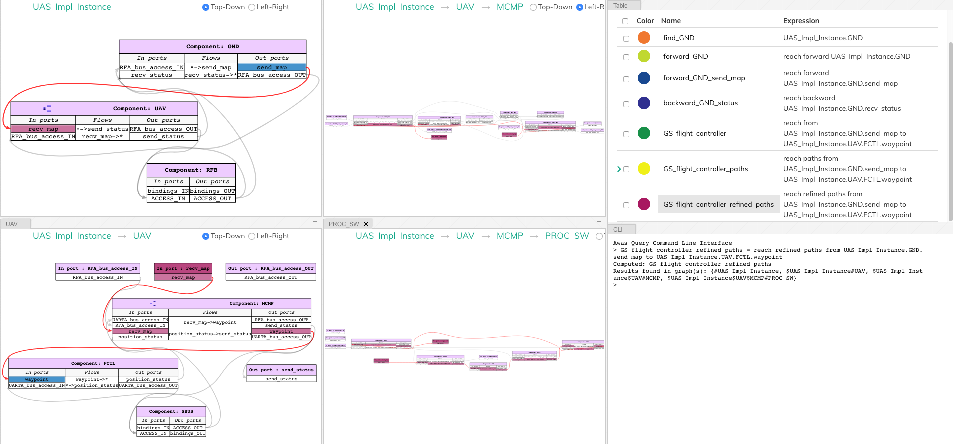
Using the previous query, Awas can capture the information flow between a source and destination, and yet, there are multiple ways information can flow from source to destination. If one wishes to enumerate all the individual paths, they can alter the above Awas query as follows.
GS_flight_controller_paths = reach paths from UAS_Impl_Instance.GND.send_map
                                           to UAS_Impl_Instance.UAV.FCTL.waypoint
|
The addition of the term paths instructs Awas to enumerate all the
paths. This action suddenly converts the simple reachability problem into an
exponentially complex problem as there can be an infinite number of
paths if there is a cycle in the graph. Our solution to this problem
is to enumerate all the paths without cycles and paths with all the
relevant cycles. For example, suppose there exist a simple
path A, i.e. path without any cycle. Furthermore, assume there are
cycles in the graph, and the nodes of the cycles overlap with the nodes
of the path A. Then we create a complex path with all the nodes of the
path A and the cycles whose nodes overlap with path A.
In the query view, you can see a little arrow in front of the query
name which indicates the existence of more than one path. Clicking the
arrow will show the list of paths. If one wishes to view only the
paths that do not contain cycles, then they can use the keyword
simple.
GS_flight_controller_simple_paths = reach simple paths from UAS_Impl_Instance.GND.send_map
                                                         to UAS_Impl_Instance.UAV.FCTL.waypoint
|
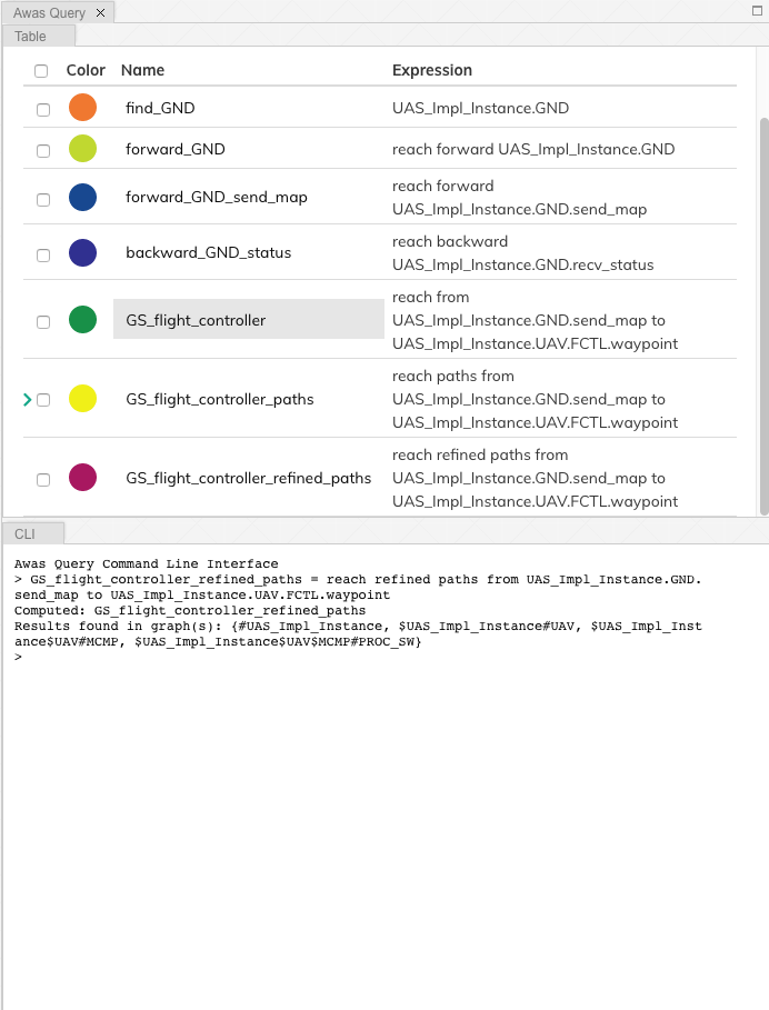
The result of the above query list three paths. Yet, we know there is
only one path from the ground station send_map to the flight
controller waypoint. This doesn’t mean Awas is incorrect. Awas is
producing all the paths which include paths that flow using
intra-component flow rather than the inter-component flows in the
sub-graph. To obtain only the refined paths, one can use the term
refined in the query.
GS_flight_controller_refined_paths = reach refined paths from UAS_Impl_Instance.GND.send_map
                                                         to UAS_Impl_Instance.UAV.FCTL.waypoint
|
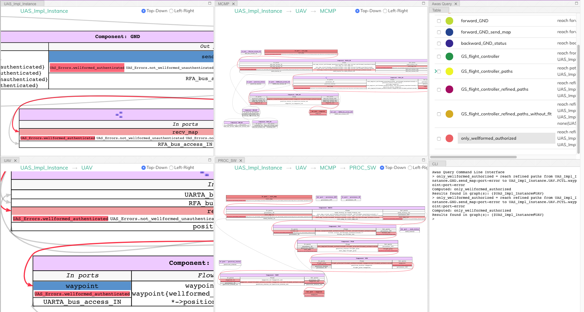
2.4.4.3. Path Based Filter
What if only some of the paths listed are of interest to the user? Alternatively, what if the user wishes to see only the paths flowing through a component of interest. In these situations, the filtering capability of Awas can come in handy.
- Query 4
When the ground station is sending the map, is it always flowing through the filter component?
The filter component in the
PROC_SWsubsystem filters out the maps that are not well-formed. A User can check this by asking is there a path from ground station to flight controller without going through the filter component. If there are no paths found then we can conclude that all the paths flow through the filter component. If a path exists that does not flow through the filter, Awas projects it on the graphs and presents the list of Awas graphs containing the result.
The following Awas query can answer Query 4.
GS_flight_controller_refined_paths = reach refined paths from UAS_Impl_Instance.GND.send_map
                                                           to UAS_Impl_Instance.UAV.FCTL.waypoint
                                                              with none(UAS_Impl_Instance.UAV.MCMP.PROC_SW.FTL:port)
|
Clicking on the query name from the query view table will cause a
The result is empty message to appear at the bottom right of the
screen.

There are a few new terms contained the the previous query:
none: This term filters the paths that do not contain the node, port, or error token specified. Similarly, there are two more terms:all: This term filters the paths containing all of the node, port, or error token specifiedsome: This term filters the paths containing at least one of the specified node, port, or error token
:port: This term pulls out all the ports from a component. Similarly one can specify the following self descriptive terms:node:port-error:in-port:out-port:error:source:sink
2.5. Risk Analysis
With the help of the error token propagation mechanism, the user can model the error behavior of the system. Using Awas, the user can compute the flow of errors in the system and may pose the following questions:
- Query 5
Is there a possibility of a hazardous situation arising throughout the system operation?
- QUery 6
What are the root causes of a specific hazardous situation?
In our UAV system, we do not have any defined safety constraints yet. However, we do have some of the security-related properties. In the UAV system, one of the security property is that only the authorized party can communicate with the UAV. We can abuse the AADL EMV2 language constructs to model these simple properties and use Awas on top of it.
- Query 7
Do only authorized and well-formed maps reach the flight controller?
We can check this using Awas by the following query:
only_wellformed_authorized = reach paths from (UAS_Impl_Instance.GND.send_map:port-error)
                                           to (UAS_Impl_Instance.UAV.FCTL.waypoint:port-error)
To view the results, first, we have to enable the view errors
checkbox in the view settings. Clicking on the query name form the
query view, we can notice only the wellformed_authenticated token
is highlighted. This shows neither unauthenticated nor
not_wellformed reaches the flight controller.
Also notice the use of port-error term instead of listing each
error token in the query. The following query’s behavior is identical to Query 7.
only_wellformed_authorized = reach paths from UAS_Impl_Instance.GND.send_map{UAS_Errors.wellformed_authenticated, UAS_Errors.not_wellformed_unauthenticated, UAS_Errors.not_wellformed_authenticated, UAS_Errors.wellformed_unauthenticated}
                                           to UAS_Impl_Instance.UAV.FCTL.waypoint{UAS_Errors.wellformed_authenticated}
2.6. Query Language Grammar
modelFile
    : model EOF
    ;

model
    : queryStatement+
    ;

queryStatement
    : ID '=' queryExpr
    ;

queryExpr
    : 'reach' reachExpr ((('-' | 'union' | 'intersect') queryExpr) | ':' filter)?
    | primaryExpr ((('-' | 'union' | 'intersect') queryExpr) | ':' filter)?
    ;

reachExpr
    : ('forward' | 'backward') queryExpr
    | 'from' queryExpr 'to' queryExpr
    | ('refined')? ('simple')? 'paths from' queryExpr 'to' queryExpr 'with' withExpr
    ;

withExpr
    : ('some' | 'all' | 'none') '(' queryExpr ')'
    ;

primaryExpr
    : nodeNameError
    | '(' queryExpr ')'
    | '{' nodeNameError (',' nodeNameError)+ '}'
    ;

filter
    : node
    | port-error
    | port
    | in-port
    | out-port
    | error
    | source
    | sink
    ;

nodeNameError
    :  nodeName error?
    ;

nodeName
    : ID('.' ID)*
    ;

error
    : '{' errorId (',' errorId)* '}'
    ;

errorId
    : ID ('.' ID)*
    ;

ID
    : ([A-Z] | [a-z]) ([A-Z] | [a-z] | [0-9]| '_')*
    ;
2.7. Known Issues
High page load time: Currently, the graph rendering and the graph cycles are computed during the page load and when enabling or disabling the
View
binding edges
. Therefore, for a large model, this may take a while to computeSolutions in development:
Use web workers to render in the browser parallelly
Launch a local server from the OSATE plugin, upon opening the Awas visualizer, process the graphs in the server rather than the browser
Warning
Do not perform path queries when the
View binding
edges
option is enabled. For a large system with a lot of binding edges, this may take a while to compute.Regular expressions to filter the paths
Solution in development:
Currently the query language supports regular expression. However, the underlying algorithms are in development
AADL EMV2 supports state transformation and component and compound error behaviors.
Solution in development:
As a first step, weakest precondition calculus is being developed on top of Fault Propagation and Transformation Calculus(FPTC)
Long term goal: Discharge the query specific sub system to model checkers e.g. AltaRica, etc.
Some browsers may restrict images or script elements when opened as a local HTML files